Saturday, November 21, 2009

Stainless steel conical beer fermenter Pt.8

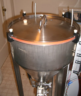
The beer fermenter project is finally ready for its first batch of beer. I bought a soft silicone strip from McMaster and cut a scarf joint in it. The diameter of the finished ring matches the lid on the fermenter.


I did some testing and verified that standard silicone adhesive would bond the red silicone rubber strip very well. I am pretty sure that if tested to destruction, the glue joint would break before the rubber itself would, but it still seems tough enough for this application.

I also welded my stainless cooling coil into the lid.


I made some Delrin clamps to keep the lid held tightly onto the tank. The silicone rubber is very soft which helps easily make a seal with minimal clamping pressure. I clamped it all up, shut both valves, and sucked some air out with my lungs. I could feel the vessel holding the vacuum that I created, so I assume the setup is essentially air-tight.

OK, so now it's time to brew some beer! Any recipe suggestions?

Friday, November 20, 2009

Installing Bluetooth audio in my car with a Motorola s705

I am nearly done with my project to create a seamless way of playing music that is stored on my computer in my car. I bought a Motorola s705, which is a Bluetooth audio receiver with headphone jack. It is capable of operating as a standard phone headset and also capable of receiving high-quality audio. First, let me review the s705 itself:

I easily paired the s705 with my HTC G1, and was able to play music through the s705 with no trouble. The sound quality was extremely good -- significantly better than the G1's own headphone adapter. It appears the high-pass filtering that the G1 uses on its own audio stream are thankfully not also used on the bluetooth high-quality audio stream. I could not hear any compression artifacts, and the sound quality remained top-notch as I walked up to about 15 feet away from the phone. I did not test the s705's battery life. I accidentally turned on the FM radio a few times, and I wish that feature could be disabled. The only negative thing is that the s705 and G1 sometimes do not connect to each other after being separated, then brought back together. Sometimes, they will only establish a phone audio connection and not a high-quality (A2DP) connection. Turning the phone off and on (or going into airplane mode and back) always fixes the problem. Turning the s705 off and on sometimes fixes the problem.


So after I decided the s705 would probably do the job, I took it apart (of course). I needed a way to remotely control the s705 power (to have it turn on everytime I started the car, and off when I shut car off), and also a way to allow it to charge its own battery while not running the car battery down.

In order to turn the s705 on or off, the power switch must be held down for three seconds. One side of the power switch would go high (about 4 volts) when the switch was pressed. Thus, I could control the device's power state by sending it a 4 volt pulse that lasted three seconds. My first plan was to use an Atmel AVR microcontroller and use a feedback circuit so that the AVR would know whether the unit was on or off. I had difficulty finding a reliable logic signal on the s705 circuit board that could be used as an on/off indicator. I was also having difficulty with the Atmel IDE that night, so I scrapped it, and decided to use two basic timer circuits (a 555 and 558 chip). The circuits send a pulse when the car turns on, and another pulse when the car turns off. It's possible for the device to become out of sync, but I don't think it will happen. The circuit uses a MOSFET whose gate is driven by a capacitor-resistor network and charged by the "on" signal from the car stereo. This way, the device will draw essentially zero current after the gate discharges and the MOSFET turns off. I've configured the capacitor value so that the circuit stays powered for 15 seconds after the car turns off.


I also wanted to sneak the audio wires out the back of the unit instead of using the headphone jack on top. I figured this would look a lot nicer when I mounted the unit on my car's dashboard.


I used the s705 shirt clip to attach it to an unused switch plate in my 1992 Honda Civic. It fits right next to the rear defroster switch.

The row of header pins have the following signals:
1. gnd
2. +12V always on from the battery
3. +5V signal from car stereo when the aux input is active
4. audio signal gnd
5. audio left
6. audio right

The audio connections go to my car stereo "aux input" which I described in another post:


The shirt clip was ABS plastic as was the switch dummy plate. I used some Weld-On #16 glue which will very securely bond ABS plastic.

It's a pretty clean installation. I've just finished it, and I'll let everyone know how it works in day-to-day use. So far, my tests in the driveway have been really great -- just step into the car and turn on the stereo, hit play on the s705, and the music starts. I don't even have to take the phone out of my pocket.

Thursday, November 19, 2009

Adhesive for polypropylene and other low-energy surface plastics

I recently had the task of gluing two pieces of polypropylene plastic together. It sounds easy, but polypropylene is a plastic with very low "surface energy" -- meaning it's difficult for most adhesives to "wet" the surface and make a good bond.

This problem of not being able to wet the surface can be seen when dripping water on a recently waxed car. The water forms beads and quickly rolls off the surface. If the car's surface has not been waxed in a long time, the water droplet may stick to the surface and form a sheet or stream of water flowing on the surface. The difference is that the wax provides a much lower energy surface to the water, which has a difficult time sticking to the wax and forms a bead and rolls away.

Plastics with low surface energy (polypropylene, polyethylene, etc) are used for food containers and other vessels because of their mechanical properties and also their inert surface that allows liquids to easily roll off. So, how to glue them? I searched the web and found this product:

3M Scotch-Weld DP8005. It has some magical composition that allows it to wet very low energy surfaces.


It's pretty expensive -- a little over $20 at McMaster, plus the special plunger (another $8). The tube of adhesive and plunger are intended to be used in a dispenser that works like a caulk gun. They also sell a mixing tip that swirls the two parts of the adhesive before dispensing. That's all fine, but I prefer to just mix with a nail on a piece of paper. I bought only the tube and plunger and had no difficulty dispensing, mixing then applying with a nail.

The adhesive itself is pretty weird. It's gritty, like it contains tiny glass beads or sand. I applied the adhesive to my project (polypropylene bottle and flat slab of polypropylene), and put the pieces with very light clamping pressure in an oven at about 80*F for about six hours. I shut off the oven and went to bed. The overnight temperature in my shop was probably 50*F.

The next day, I took the parts out of the oven and was glad to see the adhesive worked very well. It made a very strong bond -- strong enough for me to drill and tap two holes with 1/8" pipe threads in the 1/4" thick slab that I glued to the bottle. The plastic showed no signs of coming loose. I made six bottles like this, but didn't have a spare bottle for destructive testing.

Wednesday, November 11, 2009

DIY aux input cable for Kenwood car stereos

In order to achieve my master plan of abandoning CDs and converting entirely to digital/wireless music, I need to get an audio stream into my car stereo. It is a Kenwood kdc-mpv619. The front of the stereo has no input jacks. The back has output RCA plugs, but no inputs. The only way to get a signal into the stereo is to use the CD-changer connector. This is a 13-pin DIN connector that contains pins for the audio signals as well as CD changer control signals. Around the year 2001, Kenwood realized that people wanted to use the connector for aux input and started to sell an adapter ( CA-C1AUX ) to convert the 13-pin DIN into a pair of RCA input jacks. Prior to 2001, Kenwood models would not accept audio on the DIN connector until it had established digital communication with the CD changer. I know this because I had to get a CD changer and hi-jack the audio lines for an older Kenwood stereo that I have. Anyway I made a copy of the C1AUX adapter, and also helped myself to the power lines that are supplied in the DIN connector.http://pinouts.ru/Home/kenwood_head_pinout.shtml

The resistor is necessary to indicate that there is something connected, and that the stereo should make "aux" available in its menu of input selections.


So, it all worked fine, but the sound on the G1 was still horrible. No bass. No treble, but there didn't seem to be much distortion. It actually sounded pretty clean.

The next step will be to use a bluetooth receiver to feed audio into the car stereo.

Making twisted wiring harnesses with a hand drill

My dad learned this trick from a stereo installer when he worked at a Honda dealership. If you use similarly-sized wires, the resulting twist pattern is very uniform and professional-looking. Cut off a bunch of pieces of wire, then stuff all of the ends into a the drill chuck and clamp it down. Start the drill turning, and use your other hand to keep tension on the wires.

In this case, I made a wiring harness with a stereo audio cable and two power conductors.

Tuesday, November 10, 2009

Rooting and modding an HTC Dream (Google G1)

This project all started with my plan to abandon music CDs and use my G1 phone to carry all of my music. Here's how my ideal situation would work: When I get in my car, I would like to press a button and hear a series of random songs from my music collection that is stored on my computer. Note that I didn't say anything about connecting wires, syncing, downloading, looking through settings or album lists, etc. In the ideal plan, the music would all be handled seamlessly without any thought on my mind except "play".

By the way, I have been using MediaMonkey to handle my music, and I really like it:
http://www.mediamonkey.com

The G1 is a very flexible device, so I figured this would be no problem. However, there are problems. First, the audio quality coming out of the usb->headphone jack adapter on the G1 is truly dreadful. I am not being a stuck-up about this. I mean it's just plain bad. The sound has no bass (it seems anything below 150Hz is completely gone). There are a lot of compression artifacts evident in cymbal sounds, and the high-mids are unusually harsh-sounding. Finally, the overall amount of signal coming out of the headphone jack is very low. Before anyone accuses me of using low-quality MP3, let me say that I made these MP3 myself from CDs and used 320kbit for some test files. They are good MP3 and sound perfectly fine on normal sound systems.

So, connecting the G1 to my car's sound system via a headphone jack, while slightly inconvenient may not work at all because of the low quality. This prompted me to wonder if the Android software had any control over the sound output. As a matter of fact. It does, and it's possible the designers purposefully cut everything below 150Hz for use with speech-only audio.
http://forum.xda-developers.com/showthread.php?t=517745&page=120
Ah, nothing like a 120-page thread. I'm sure it will only take a few hours to read it.

Anyway, the short story is that a developer named meltus has found three audio files in the system/etc directory of the android operating system that have some effect on the sound processing. I was intrigued and wanted to edit the files myself to see how much of the audio quality was dependent upon software. Unfortunately, the android system will not allow anyone to edit system files (even me, the owner of the damn phone). I instantly decided to "root" the phone so that I could investigate the full potential of the device.

Gaining root access is possible on the G1 by a few different ways, but the information available on the web is sketchy. There are only two groups of people who root their phones: 1. Serious developers who are so into Android, that they don't have time to explain the process to newbies 2. Newbies who want root access but don't know what it is. There is a major echo chamber on the web just filled with mindless stupid comments from people hacking away at their phones. I am not against hacking, I am only against repeating misinformation in forums and wasting bandwidth by repeating hearsay over and over again.

Anyway, I followed Cyanogen's instructions, and didn't have any problems at all:
http://wiki.cyanogenmod.com/index.php/Full_Update_Guide_-_G1/Dream_Firmware_to_CyanogenMod
This guy deserves major props for writing a clear, concise set of directions.

The process of downgrading to RC29 is not that hard, and the whole process took less than an hour.

So, here it is, and I know have complete control of my own phone.

The next steps will be to see how much better the audio quality can be made, testing bluetooth high-quality audio, syncing MP3 over Wifi, installing a bluetooth receiver in the car, etc.

Saturday, November 7, 2009

Improved level sensor for the DIY aquarium top-off project


In my
original post regarding an automatic water top-off system for aquariums, I designed a sensor head that consisted of a plastic rod with a set of pocket holes drilled at the tip. The holes were diametrically opposed and angled so that they intersected at a point about 1cm in front of the plastic rod face. I inserted a plastic fiberoptic into each of the holes, and the system would allow sensing a liquid level surface by measuring the amount of light reflected off the surface. If the liquid covered the two probes, all of the light would be scattered off into the liquid and the signal would be almost zero. When the level fell below the fiber ends, the reflected light would trigger the top-off pump.

This system worked very well until nearly flooding my house a couple weeks ago. By extreme luck, I happened to be sitting near the aquarium when an air bubble got trapped between the two fiberoptic ends. This caused the top-off pump to run even after the water level had risen higher than the sensor head. I heard the tank dripping water and quickly shut off the pump. Following this event, I decided to improve the reliability of the sensor.

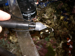
I did some searching for commercially-built liquid level sensors and found that many of them operate by submerging a prism and measuring the amount of total internal reflection. When the prism is submerged in liquid, the light will pass out of the prism and into the liquid. When dry, the prism will reflect most of the light internally. By positioning the fiberoptics symmetrically, the light signal will be drastically changed by the liquid surrounding the prism.


I machined and polished a piece of acrylic into a point. Then I drilled two holes that would snugly hold the fiberoptics. I mounted the whole thing on a Delrin rod.

This sensor should be much less sensitive to air bubbles, snails, dirt, etc than the previous model. For the next week, I'll be monitoring the top-off system and manually controlling the pump. If it looks good, I will connect the pump and let everyone know how it works.

Monday, November 2, 2009

Drinking glass carrier

This project was inspired by a brew-pub in San Francisco called the Beach Chalet. They have a "beer sampler" on their menu that includes small portions of six of their beers. The beers are served in small glasses that fit into a wooden rack. Neat!


It's been a while since I have been to the Beach Chalet, so I don't remember their wooden sampler rack in detail. That's just as well, since I wanted to design my own anyway. I used maple, walnut, and bloodwood (the same woods that I always use) in this project. The central brass rod is threaded from its midpoint to the bottom and it passes all the way through the wood top and base. A brass nut and washer clamp the top of the rack and another washer and nut are located under the base. The set of nuts clamp the top to the base with no danger of a glue joint breaking (the end-grain to side-grain glue joints aren't very reliable). The brass rod has a hole drilled through it near the top, and a small brass ring is mounted in it for easy carrying. The ring was sealed shut with silver solder.